cd:tocdepth: 1
1 Abstract
This tech note provides a description of the Exposure Time Calculator for the Collimated Beam Projector (CBP), which is part of the main telescope Calibration System. It includes results of expected exposure times for a range of pinhole masks in each LSST filter.
2 Overview
The Collimated Beam Projector (CBP) is a novel calibration device used to determine the throughput of the LSST optics. It is fed with a tunable laser so that we can measure the throughput across all LSST filters. We want to determine the required exposure times of the LSSTCam to achieve a required Signal to Noise Ratio to develop the necessary calibration products.
Of the following diagram, we will cover the Laser+Fiber lightsource, CBP and LSST boxes. Other elements of the calibration ETC can be found in the Flatfield Calibration ETC Tech Note.
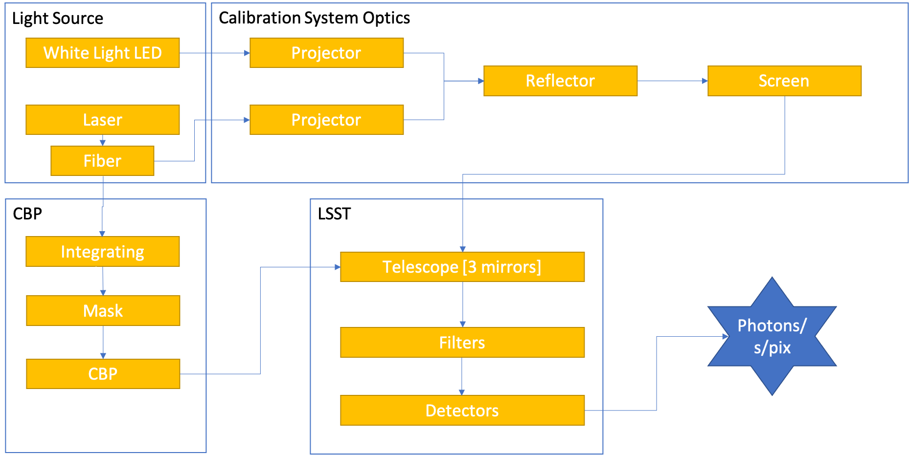
Figure 1 ETC Overview
3 Laser Input
- Parameters:
laser_file: filename that contains the Watts/nm from the laserdecrease_expected: This is the percentage decrease from the values in thelaser_file. This should be zero if thelaser_filescontains measured levels.
We are using the Ekspla NT242 currently. It is possible that we may have a backup laser with a different output profile. Currently, we are using PGD151_NT242.txt, which is the expected levels from the distributor. We will want to update this with measured values.
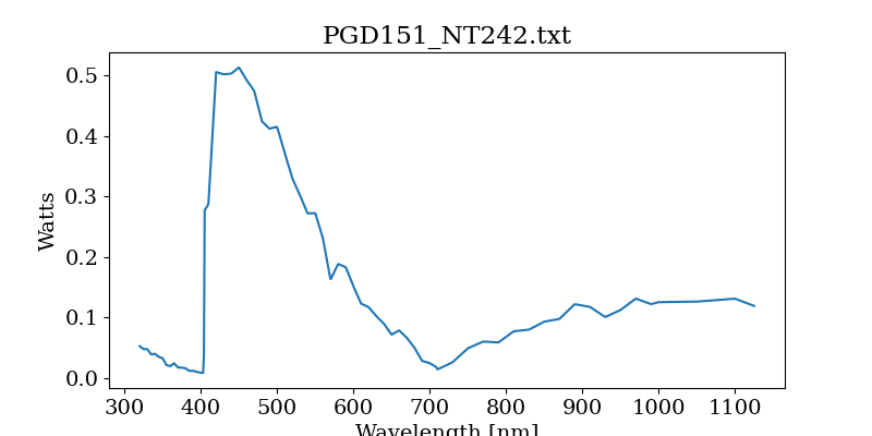
Figure 2 Output of NT242 laser
Note
This ETC assumes the laser will be used in continuous mode. It will likely be used in burst mode.
3.1 Fiber Attentuation
- Parameters:
fiber_length: Length of fiber from the laser to either the CBP or the flatfield projector.fiber_type: This is the type of ceramoptic fiber we expect to use.fiber coupling: This is the throughput decrease based on the coupling between the fiber and the laser.use_fiber: Whether or not a fiber will be used [True]
Based loosely on LTS-664, I estimate that the fiber will run ~15m from the laser to the projector.
Likely, will get this fiber from ceramoptic: https://www.ceramoptec.com/products/fibers/optran-uv-/-wf.html.
The attenuation (dB/km) for several kinds of fibers was sent to me by Ceramoptic (email) and WFNS was recommended.
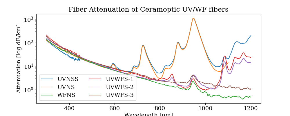
Figure 3 Attenutation of ceramoptic UV/WS fibers.
Tranmission of the fiber is then calculated:
Based on initial measurements with a NA=0.22 fiber on April 11, 2023, the fiber_coupling is estimated to be 0.8 across wavelengths.
4 CBP Throughput
The laser light travels from the laser to the CBP via fiber optic. This runs to a 6” integrating sphere, which also has a photodiode attached so that we can monitor the relative light level. The light from the integrating sphere then travels through the mask, which is positioned on the focal plane of the cbp. The CBP then collimates the light and sends it towards the LSST telescope and camera.
The total throughput of the CBP consists of that of the integrating sphere, the mask efficiency and the efficiency of the CBP optics (mirrors and lenses) depends on the size of the mask pinhole.
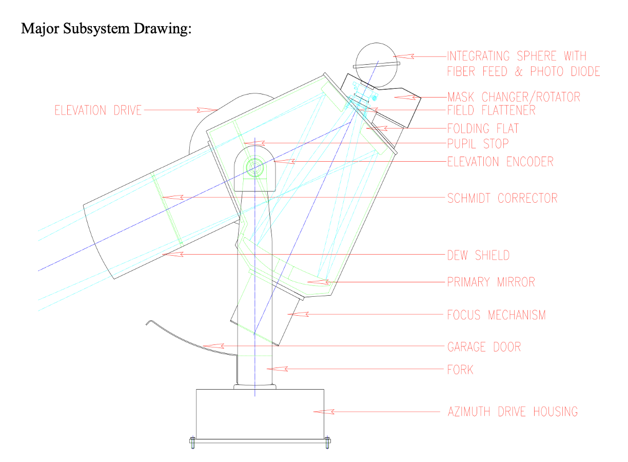
Figure 4 Layout of CBP
4.1 Integrating Sphere
- Parameters:
sphere_reflectance: Reflectivity of integrating sphereexit_port_diameter: Size of the exit port of the integrating sphere (inch)port_diameters: List of the port diameters on the integrating sphere, including the exit port (list in inches)sphere_diameter: Diameter of the integrating sphere (inch)
Currently using 3P-GPS-060-SF AS-02266-060 from Labsphere, which uses Spectraflect coating on a 6 inch diameter sphere with and exit pupil of 2.5 inches and two 1 inch ports, one used for input of the fiber and the other for the photodiode. I am assuming a mean reflectance values of 0.985 for the Spectraflect.
The following calculations are taken from here the Labsphere Guide to Integrating Spheres.
Calculate the surface area of the inside of the ingrating sphere after having converted the \(D_{sphere}\) to radius in m from inches (\(r_{sphere}\))
Calculate the total area of the ports in the integrating sphere, where \(r_{i}\) is the radius of each port).
Finally, calculate the intensity of light exiting the integrating sphere, by multiplying Ls by the flux incident on the integrating sphere.
4.2 Mask Efficiency
- Parameters:
pinhole_size: Size of the mask pinhole [m]distance_to_mask: Distance from the exit pupil of integrating sphere and mask [inches]
There are a variety of mask designs that are being considered with a range of pinhole sizes. This ETC is being used, in part, to evaluate different mask designs.
The current design has the distance_to_mask at approximately 3 inches.
When then need to determine how much light from the integrating sphere is incident on the mask.
Measure the angle from the exit pupil (\(r_{exit}\)) to the mask
Then calculate the solid angle of light making it to the maks
Finally, multiply by the area of the mask, calculated as \(A_{mask} = \pi \cdot r_{mask}^{2}\) to the get the mask efficiency.
4.3 CBP Efficiency
- Parameters:
cbp_tranmission: Tranmission of CBP optics.f_num_cbp: f/# of the CBP [2.63]f_cbp: Focal length of the CBP (m) [0.635]
The transmission of the CBP optics was measured by the vendor to be 0.55. We estimate that it is now closer to 0.5
First measure how much light from the mask is getting into the CBP:
And then multiply this by the overall transmission of the CBP optics.
5 Telescope and Camera Throughput
- Parameters:
total_number_of_pixels: 3.2e9pixel_size: 10e-6 mf_lsst: focal length of the LSST telescope (m) [10.3]
5.1 Mirror Reflectance
- Parameters:
m1,m2,m3: Reflectance for a mirror coating; options:[Unprotected-Al,``Protected-Al``,``Protected-Ag``]
There are three mirrors [m1, m2, m3] that will be coated with either Al or Ag. The full throughput will be the combination of the three mirrors, whether all have the same coating or different. The curves we are using come from a document sent directly from Tomislav Vicuna, called Final procAg-ProcAl_bareAl.xlsx.
Currently, the understanding is that all three mirrors will be coated in Protected Silver.
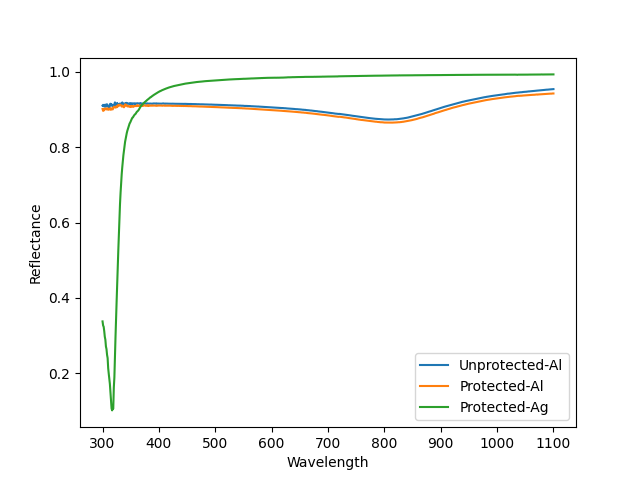
Figure 5 Reflectance of telescope mirror coatings
5.2 Filter & Corrector Throughput
Using the filter and lens throughput from the Baseline Design Throughput on Docushare.
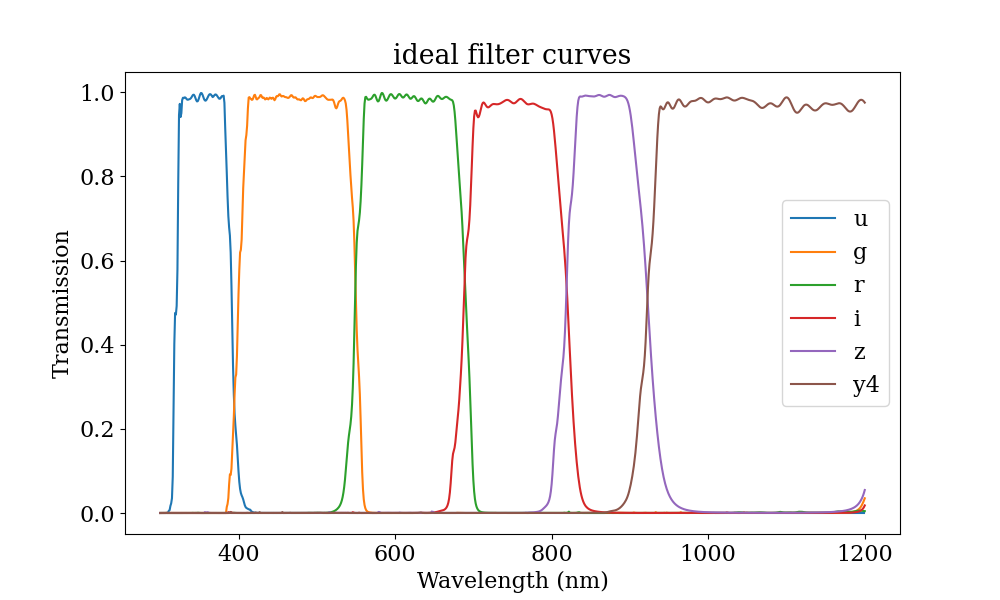
Figure 6 Ideal filter throughput
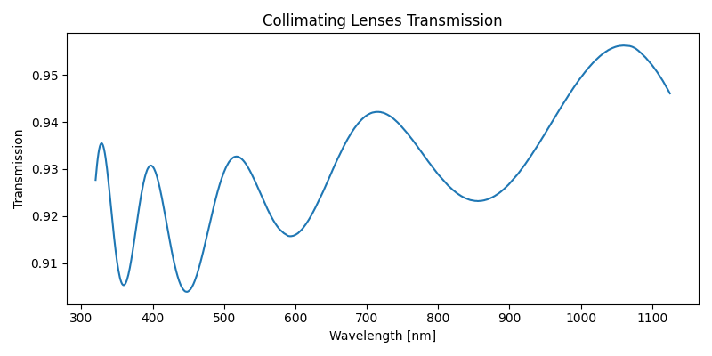
Figure 7 Total transmission of three lenses that make up the collimator.
5.3 Detector Efficiency
- Parameters:
detector_file: File with QE for the detector
Currently using the QE curve for the e2v detectors (detector_e2vPrototype.dat) from the Baseline Design Throughput on Docushare.
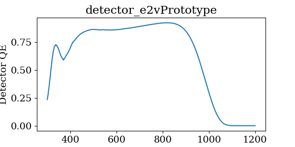
Figure 8 QE for e2v detectors
6 Readout Overheads
- Parameters:
cam_readout: readout time for LSSTCam [2 sec.]min_exptime: The minimum exposure time allowed by the camera [15 sec.]electrometer_readout: The readout time for the electrometer [not currently set]spectrograph_readout: The readout time for the spectrograph [not currently set]
The exposure time overheads are quite simplistically calculated at this time. Essentially, we can only take an exposure every 17 seconds. Therefore, if we require less than that time to reach the required SNR, the total exposure time is 15 seconds plus an additional 2 seconds of readout time. If we require more than 15 seconds of exposure to reach teh required SNR, we will add additional exposures of length 15 seconds until it is met. Each 15 second exposure requires a 2 second readout time.
I am not currently calculating the readout time required for the electrometer. This will have to be addressed very soon.
7 Exposure Time Calculator
The code for the ETC is currently being developed in https://github.com/lsst-sitcom/notebooks_parfa30/tree/main/python/lsst/sitcom/parfa30/exposure_time_calculator.
The exposure time calculator is saved in rubin_calib_etc.py and runs given a configuration file, like calib_etc.yaml.
First, photons per pixel are calculated, by taking the following steps:
Calculate irradiance from laser + fiber into the CBP integrating sphere
Multiply by the CBP transmission, which includes the integrating sphere, mask efficiency and cbp throughput to get irradiance on telescope
Calculate number of photons hitting telescope
Multiply by the telescope, filter and camera efficiency curves
Divide total photons detected by total number of pixels
Finally, Then the size of the spot is calculate for a final SNR per spot:
8 Sample Results
The following results assume a 6 inch integrating sphere using the NT242 laser used in continuous mode.
These results were generated with the calibration files 'cbp_calib_etc_11092023.yaml'.
The photon rate (photons/second/pixel) of the CBP constant relative to the size fo the pinhole.
Filter |
Photon Rate |
u |
4986.94 |
g |
253573.16 |
r |
103405.55 |
i |
45307.81 |
z |
94469.94 |
y4 |
74643.21 |
The photon spot rate does change as a function of pinhole diameter, given the magnification of 16 between the CBP and LSSTCam
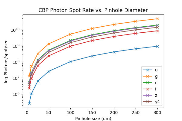
Figure 9 Mean photon rate per spot for CBP per filter as a function of the spot size
The following two plots show the photon rate per spot at every wavelength for a mask with a 150um and 5um pinhole.
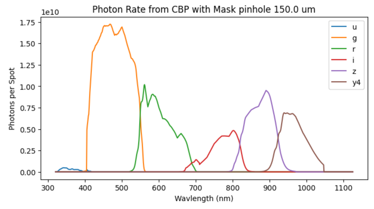
Figure 10 Photon rate per spot for CBP with 150um pinhole
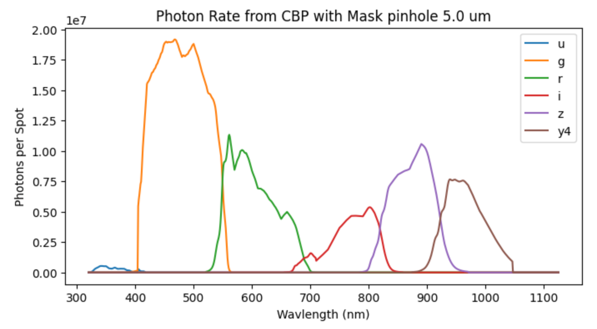
Figure 11 Photon rate per spot for CBP with 5um pinhole
In all cases, the exposure time per wavelength is on order of 1 second per wavelength to achieve a SNR of 300. If we include the fact that we can’t take an exposure more often than every 15 seconds, we are heavily dominated by the overhead time.
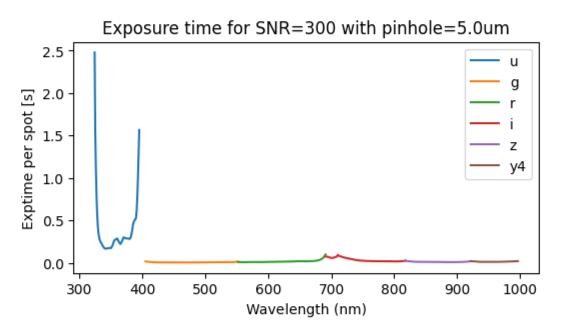
Figure 12 Photon rate per spot for CBP with 5um pinhole